The goal of our first second-semester group project was to design a unique electronic mobile device. A number of briefs were provided for us to chose from. After some inital discussion we selected 'going to an entertainment event' as our brief and decided to design a hearing-related product. Our product's basic fuction was to warn the user of the intensity of sound around them, such as loud music at a concert. For a more detailed look at the development of our ideas and the project as a whole, please read my full project summary here. This page is focused on my initial drawings and how I made corresponding 2D models using AutoCAD. Below you can see some early concept artwork. The product's phyisical form was not decided yet so I visualised a whole range of different ideas.
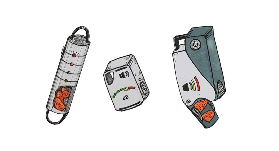
I was particularly interested in the tubular design seen above on the left. The loop on the top would allow tethering onto a belt or bag and it featured a compartment for ear defenders so the user always had a set handy. I drew up some initial 2D designs using AutoCAD, showing two different view of the product.
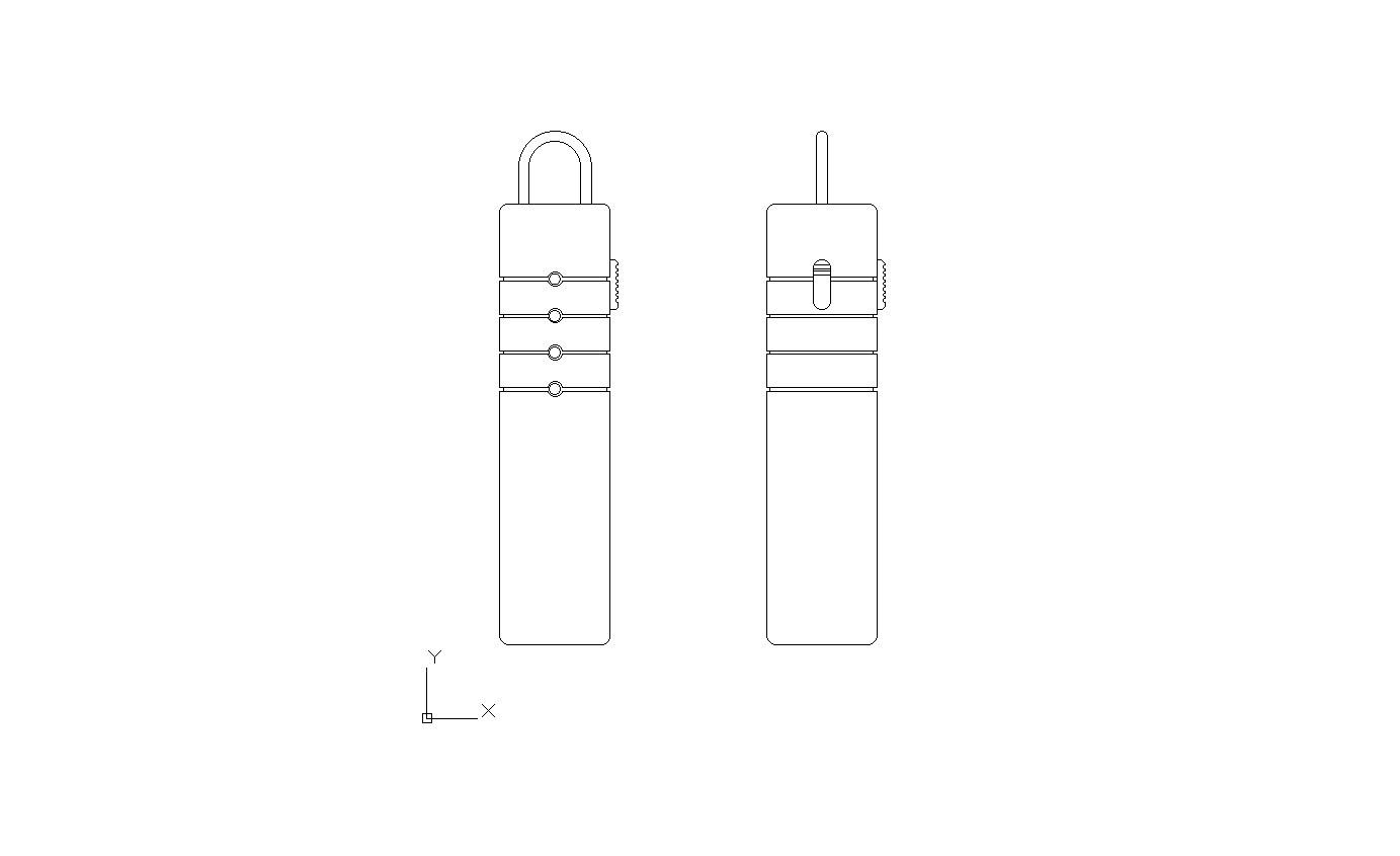
After further group discussion and evaluation of my concept, we decided to proceed in a different direction. The tubular design wasn't compact enough and we were concerned that having it hanging from a belt or bag would lead to poor sound readings and potential damage to the product. Instead we investigated designs to be worn in different places such as on the wrist. Since flexibility was desirable, I began to design a product that could be worn in different ways, something modular or convertible.
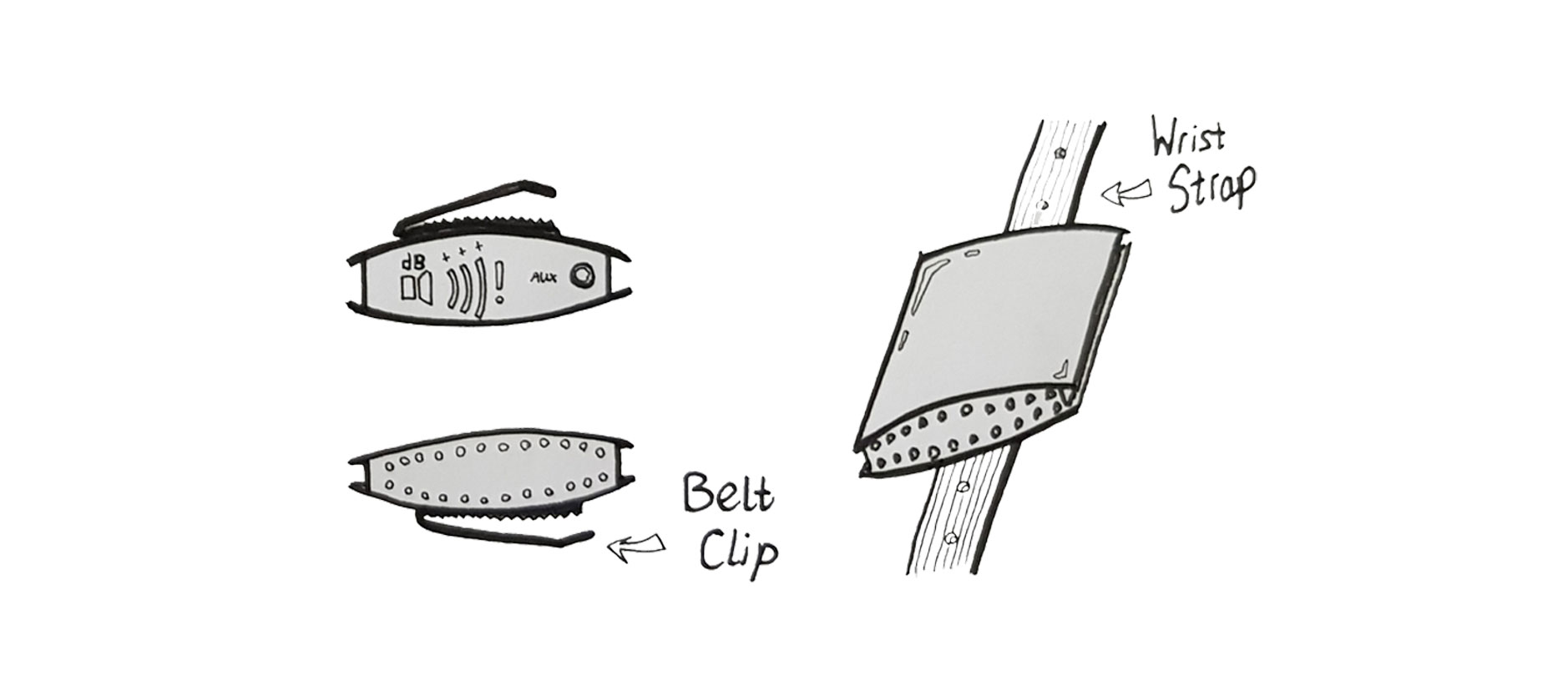
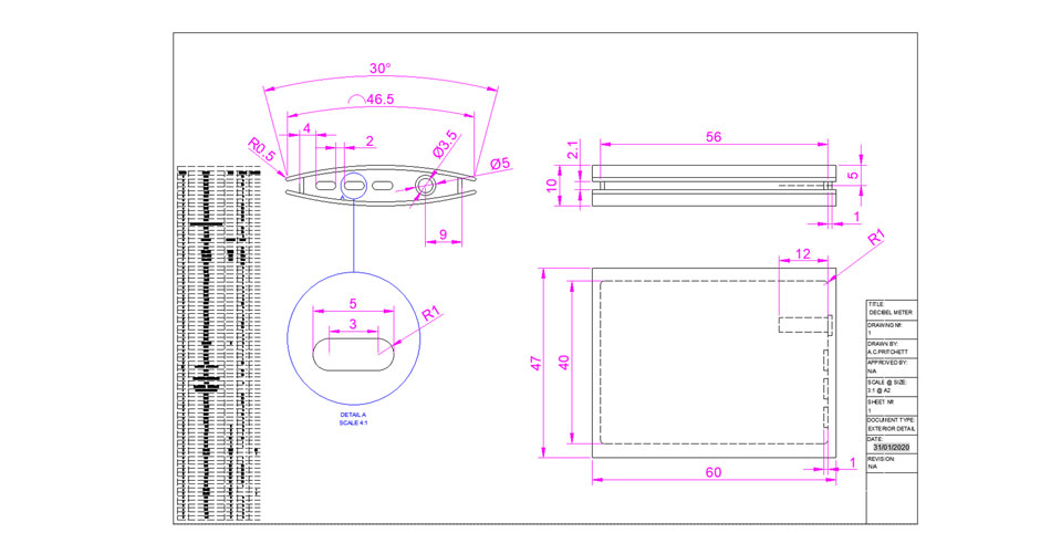
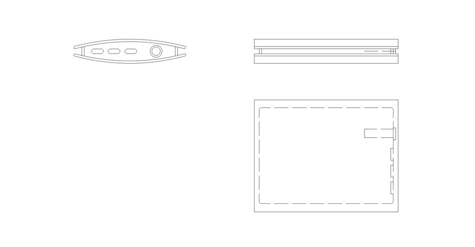
The design I came up with was compact, sleek and could be worn on the wrist or clipped over a belt or pocket. I made a set of 2D isometric drawings to show the size and shape of the product. Being relatively simple 2D drawing, the line, polyline, circle and arc tools were used extensively, combined with the trim tool to get the shapes I wanted and the mirror tool to make sure eveything was symmetrical. I used dashed lines to show hidden features like the 3.5mm aux port.
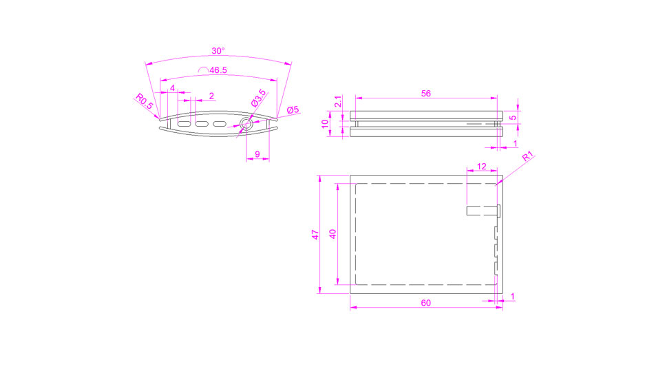
Once I was happy with the drawings and felt I had represented the necessary angles I switched to a different layer and added my dimensions in bright text so they would stand out. I predominantly used the linear, arc length and radius dimension tools to provide basic dimensions. Note that while nominal dimensions are enough to make a prototype with, drawings intended for production would need a range of geometric tolerances too. All dimensions are in mm.
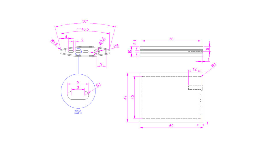
It soon became clear that I would not be able to dimension every aspect of the drawing as I had hoped, as to do so would clutter it up significantly. I therefore opted to add a 'zoomed-in' detail view to show one area of particular detail and its dimensions on an enlarged scale that would be easy to interpret.

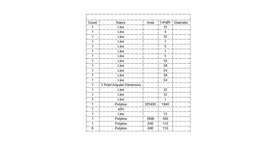
Next I made a data extraction table to list the different lines and shapes that made up the drawing. I decided to include the area, lenth and diameter fields which could potentially be used to calculate surface area, weight and material usage. To finish my detailed 2D drawing I placed it on my 2D Landscape drawing template alongside the data extraction table (the font had to be very small to fit)
