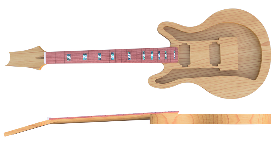
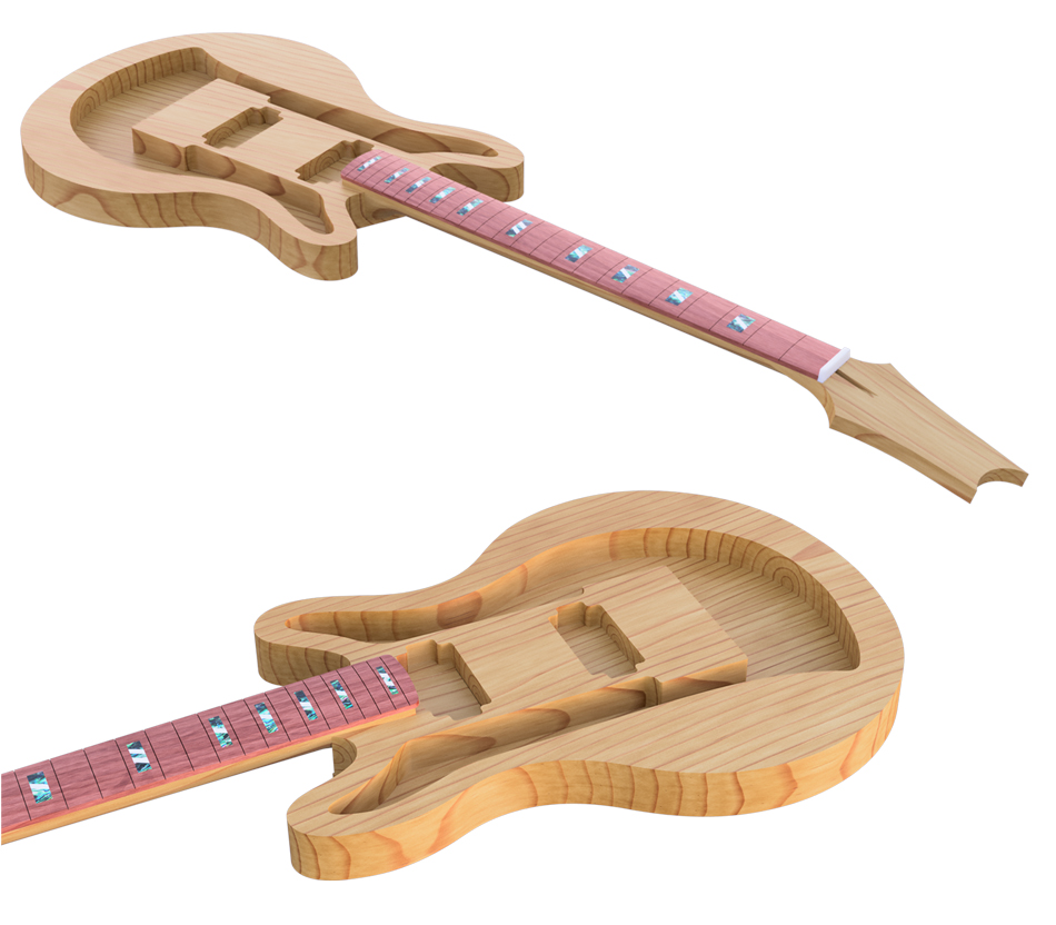
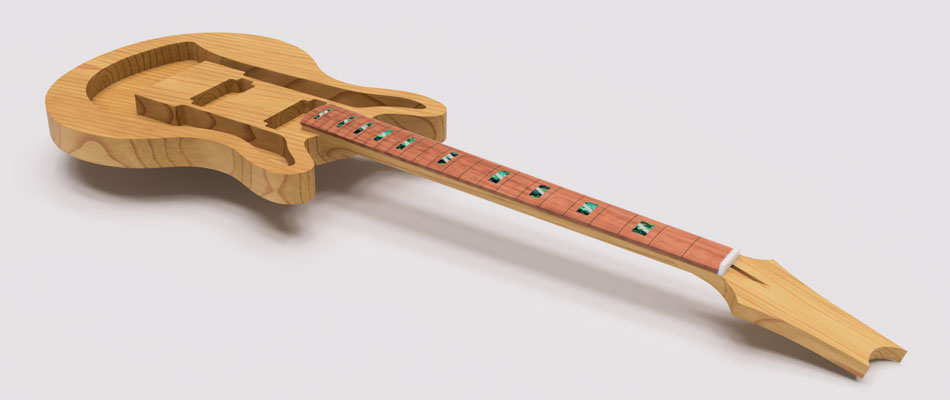
Banshee Guitars Client Project (NLT1)
Of the three modules taken in the first semester of our third year, the Negotiated Design Placement was perhaps the most important. Not only would the outcome of this module have a larger impact on our final grades than the other two modules, but it also represented the best opportunity to do some real CAD project work. In theory, this module’s possibilities were endless – we could find a relevant company or individual to work with in a physical work-experience role, collaborate on a project remotely, work on a personal project or even work on a client project arranged by the department. In reality, or at least my reality, there were few opportunities for work experience, in no doubt partly due to COVID-19 disruption and uncertainty still plaguing the industry. I had contacted numerous relevant companies to no avail - this was disheartening as I really wanted some hands-on experience, but thankfully the flexibility of this module meant there were lots of other options to explore. Towards the end of the summer break, a fellow DMD student had been generous enough to recommend my services to his uncle Simon, who needed 2D and 3D CAD services for his guitar project. The project sounded very interesting to me; it was quite different to anything I'd worked on before and offered the possibility of working on 2D and 3D models - I gladly accepted the offer, and so began a challenging and rewarding 4-month client project. Click Here to view my updated NLT1 form with details of the project.
Of the three modules taken in the first semester of our third year, the Negotiated Design Placement was perhaps the most important. Not only would the outcome of this module have a larger impact on our final grades than the other two modules, but it also represented the best opportunity to do some real CAD project work. In theory, this module’s possibilities were endless – we could find a relevant company or individual to work with in a physical work-experience role, collaborate on a project remotely, work on a personal project or even work on a client project arranged by the department. In reality, or at least my reality, there were few opportunities for work experience, in no doubt partly due to COVID-19 disruption and uncertainty still plaguing the industry. I had contacted numerous relevant companies to no avail - this was disheartening as I really wanted some hands-on experience, but thankfully the flexibility of this module meant there were lots of other options to explore. Towards the end of the summer break, a fellow DMD student had been generous enough to recommend my services to his uncle Simon, who needed 2D and 3D CAD services for his guitar project. The project sounded very interesting to me; it was quite different to anything I'd worked on before and offered the possibility of working on 2D and 3D models - I gladly accepted the offer, and so began a challenging and rewarding 4-month client project. Click Here to view my updated NLT1 form with details of the project.
First, some background on the Banshee guitar project. Simon Congdon and Simon Owen have collaborated over two guitar builds and have built a total of four guitars to date. Simon Owen is a Master Craftsman with a total of five guilds in cabinet making, and is possibly the most skilled wood & cabinet maker in the south of England. Simon Congdon is an aircraft pilot trainer and has been playing guitars for 30 years. In 2019 the two Simons built their first guitar as a project to explore the possibility of producing a guitar for professional musicians – the Banshee brand was born. Click Here to view the project brief.
Despite the approachability of my client (all communication was with Simon Congdon, which was passed through to the other Simon when necessary), I was quite anxious about the project at the start as I knew basically nothing about guitars, much less artisan electric guitar building. We decided that the best approach would be to use the remaining few weeks of my summer break to familiarise myself with the electric guitar, such as understanding the purpose of different components and how they fit together. I didn’t have to be an expert, but I knew it would be very hard to create detailed drawings and models for something I had no understanding of. Simon recommended some online resources for me to read through, such as the very comprehensive Electric Herald website which helped me understand the different styles of electric guitar and which templates are needed to form each component. While the Herald had all the specialist technical data and pre-made templates a luthier would need, Youtube was equally important as there were lots of resources showing detailed step-by-step guitar builds, which were exactly what I needed to understand how the drawings and templates would be used by Simon. Of particular interest were the guides published by the channel 'The Electric Luthier', who had a comprehensive library of electric guitar building videos for beginners. Although it was a little overwhelming to embark on a technical and very specialised project in an industry that I had no experience in whatsoever, it was very exciting and seemed like a great opportunity to experience a new style of work. I was sure it would also provide lots of opportunities to improve my 2D and 3D CAD skills - I felt that my 2D skills hadn't been used much since first year, so I was keen to relearn or refresh myself on anything I might have forgotten since then.
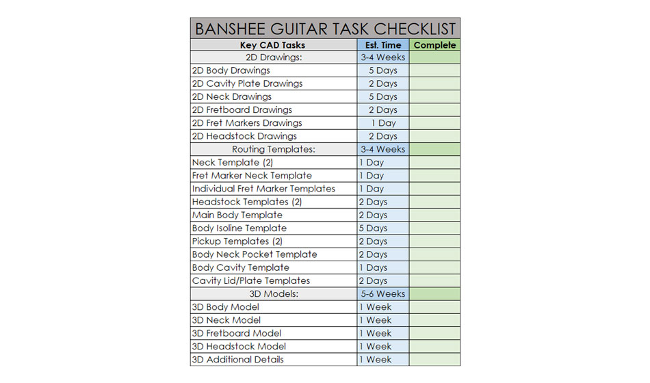
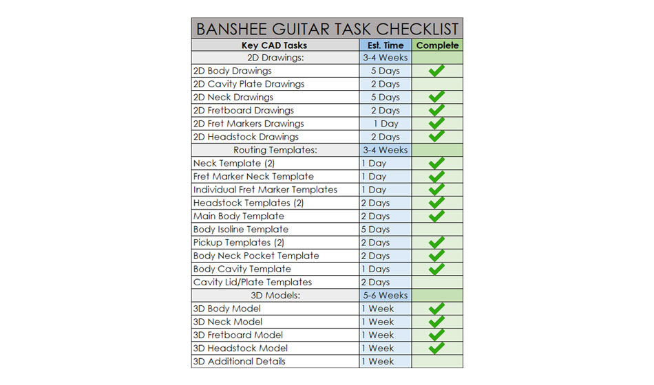
Given the number of tasks that the client needed me to complete by the end of 2021, it was very important to plan the project carefully. Time planning was especially critical as the client needed various drawings and templates produced in the right order and on schedule to facilitate the physical guitar build, which was happening in real-time alongside my part of the project. I started the planning process by producing a list of all the tasks, with an estimation of how long each would take. Calculating this was challenging because I had never worked on an instrument before, and all the particulars of guitar building were still new to me. I was able to come up with some rough estimates based on my research so far and my previous CAD experience.
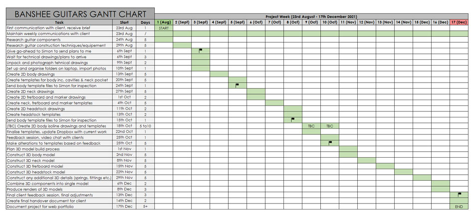
These key CAD tasks were combined with the other non-CAD tasks (such as research, administration, and communication) into a large Gantt chart so the whole project could be mapped out accurately. Important milestones were marked with a flag, which showed tasks that were both critical to my side of the project and/or critical to the actual guitar build that was running in the background. This was the first client project entirely planned and managed on my own, so I was very careful to make sure it would run smoothly – I really didn’t want to let my client down, especially since I had been personally recommended to him. The Gantt chart worked very well in organising this specific project, but failed to take into account the pressure of the other modules being conducted at the same time. Towards the end of the project I rectified this by making a master planner with all the modules present, but I should have done this at the start.
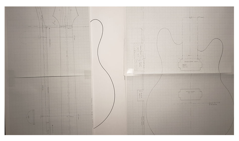
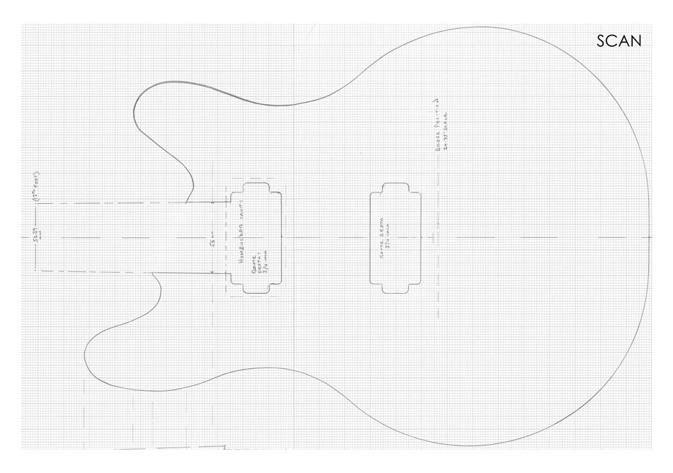
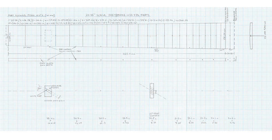
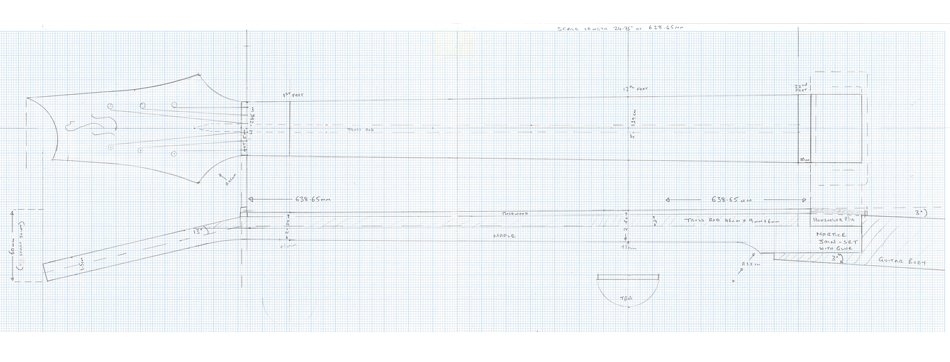
Early in September, a package full of hand-drawn plans arrived for me to work on. The designs had been drawn carefully onto graph paper with pencil, and most of the sheets had been taped together so they were long enough for the whole guitar body and neck - they were 1:1 scale and I was instructed to recreate them accurately in CAD. I was immediately disturbed by the lack of dimensions on the drawings! I have a lot of experience in technical drawing, but had never come across a series of plans with so few dimensions, nevermind any tolerances or technical data. I spoke to Simon who told me that the plans were to scale, so to directly translate them into CAD would be close enough for the purpose. How to do this with any accuracy at all would prove to be a significant challenge! Some of the plans can be seen below. They were large and numerous, quite capable of completely covering my bedroom floor.
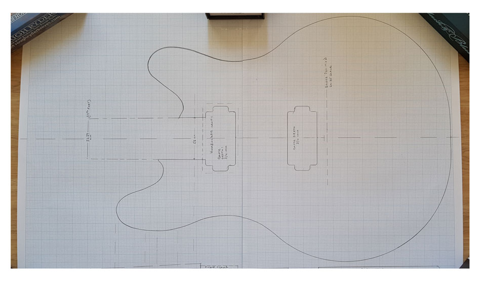
Initially, I decided that the simplest way to digitise the plans would be to take as perfect a photograph as I could, and then digitally manipulate it so it could be used as a drawing canvas in AutoCAD or Fusion 360. I did not have immediate access to a scanner, so this was the easiest way of getting the plans into my CAD software – I figured that this method would be accurate enough, assuming I could take a clear, level photograph. The plans kept wanting to curl back up into their prior state (sent in a tube), which made getting them completely flat very difficult.
Once I had a shot that I was happy with, I edited the image using Photoshop to enhance the pencil lines on the paper so they would be easier to trace around. This worked quite well, and the design was nice and clear once imported as a canvas into Fusion 360.
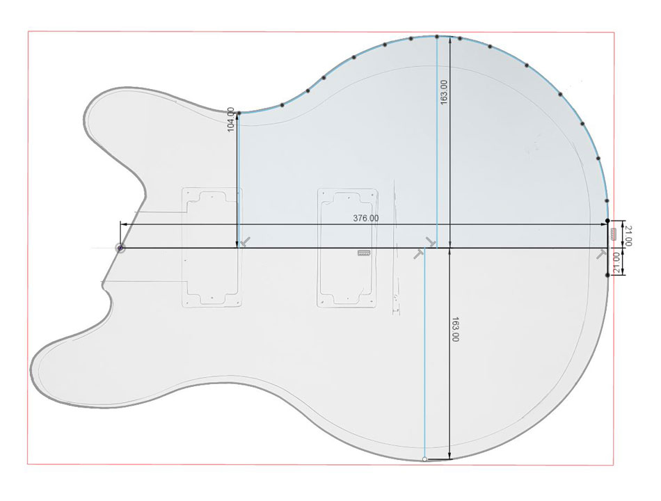
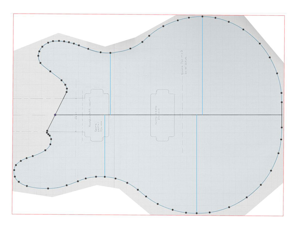
After calibrating the canvas in Fusion 360 (done by selecting two known points and entering a dimension which scales the drawing), initial results appeared to be quite good, with a fairly close match between the on-screen dimensions and the real-life measurements of the drawing. I began to carefully trace around the perimeter of the body using the spline tool.
Unfortunately, it didn’t take long for some serious issues to appear. The more I traced of the body profile, the less the dimensions matched those of the paper drawing. Keep in mind that the paper drawing dimensions were taken by hand using a ruler (of dubious calibration) since there were no actual dimensions on the plans, adding yet another layer of uncertainty to the whole operation. It was clear that the image I had taken was not accurate enough to simply trace around, and truth be told I was starting to think the project might be dead in the water – how could I make accurate models without dimensions?
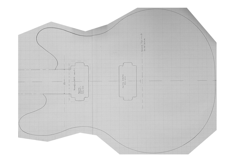
Determined to find a way forward, I took the plans up to campus and attempted to scan them instead. This was awkward because the machines were only able to scan A3 pages, so I took two scans for each drawing and stitched them together in Photoshop. This was yet another area for potential misalignment, but I couldn’t see any other way of doing it. Thankfully the scans came out much truer than the photos did, allowing me to continue to project with a fairly high level of accuracy to the drawing. Below is an example of two A3 scans aligned and fixed together in Photoshop to make one image. The improved clarity should be apparent. Click to view larger image.
I set about tracing around the new image, basically starting again which set my schedule back somewhat – it was worth it though, because my on-screen dimensions matched the paper drawings to within half a millimetre or better. It wasn’t all smooth sailing from here though. Shortly after I had finished the outline of the body, the two Simons had decided that a rounded bottom would be better than the current flat style. This alternation in itself wasn’t an issue, but the reference image I was provided was less than ideal, as seen below. I edited the image and added guide lines so I could align it with my CAD drawing properly.
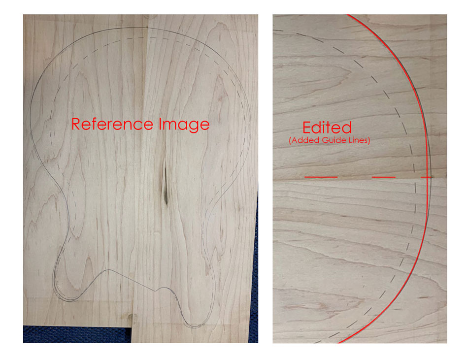
By this stage I had a good amount of experience in manipulating photos so they were suitable for tracing around, so I got the image lined up as close as I could and adapted the CAD drawing profile to match. I was concerned about accuracy, but I had to keep in mind that these drawings would be used to make templates, which would then be used to cut shapes from wood, which would then be finished by hand. Precision engineering this was not, and while that was simply the nature of a project like this, it certainly felt very unnatural to me.
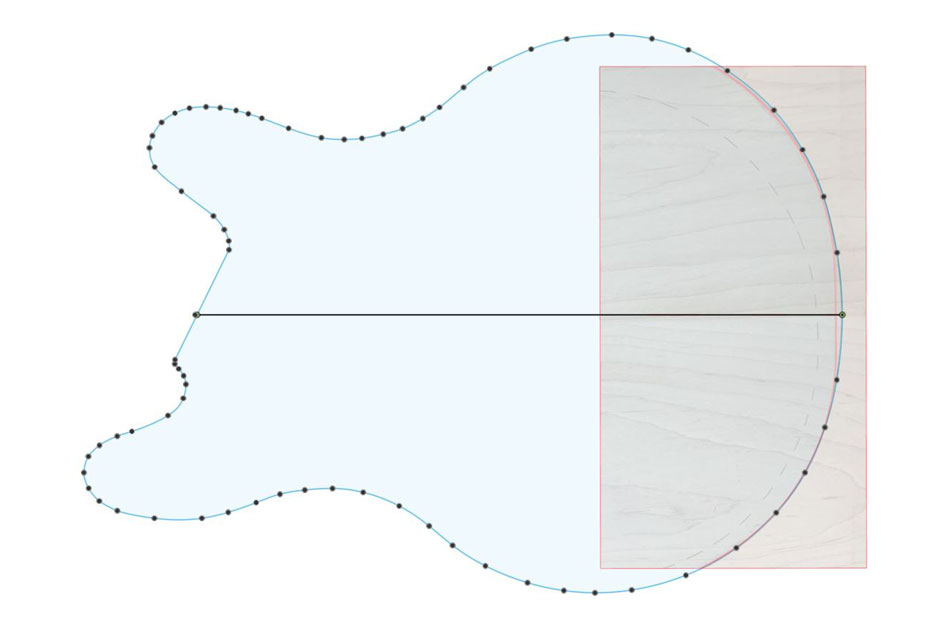
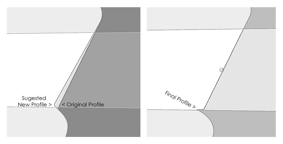
The next few weeks were filled with back and forth between Simon and I to ensure that every curve on each drawing was exactly how he wanted. This represented by far the most communication I’ve ever had with a client, amassing to over 200 emails sent between us throughout the duration of the project. Simon’s crystal-clear vision for the project was well-matched to my eye for detail. Dozens of small changes were made on every drawing, ranging from the smoothing out of curves to the subtle adjustment of an angle. Many of these alterations underwent multiple phases, like the neck joint area seen below.
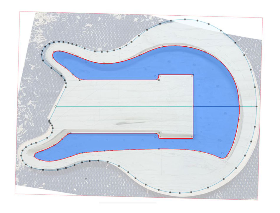
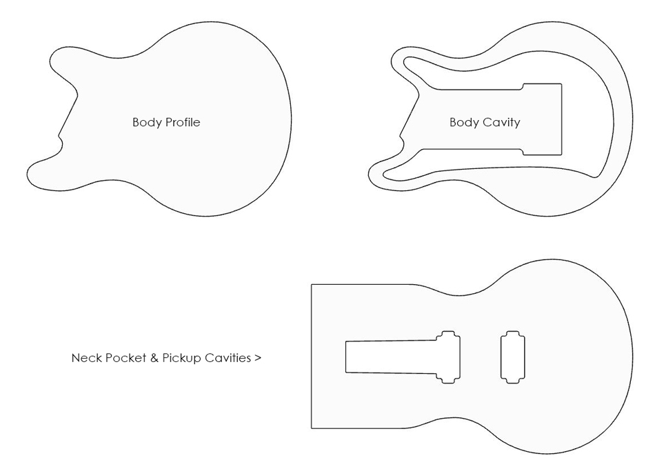
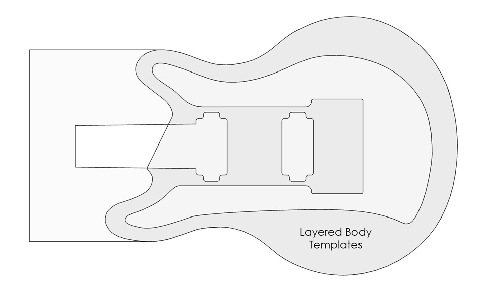
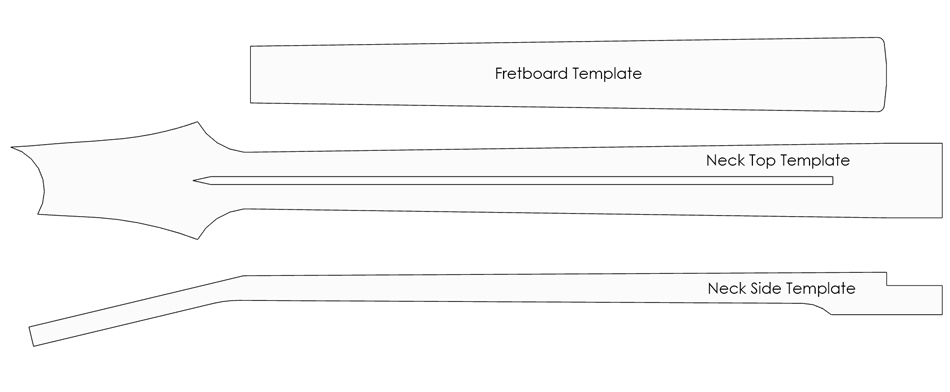
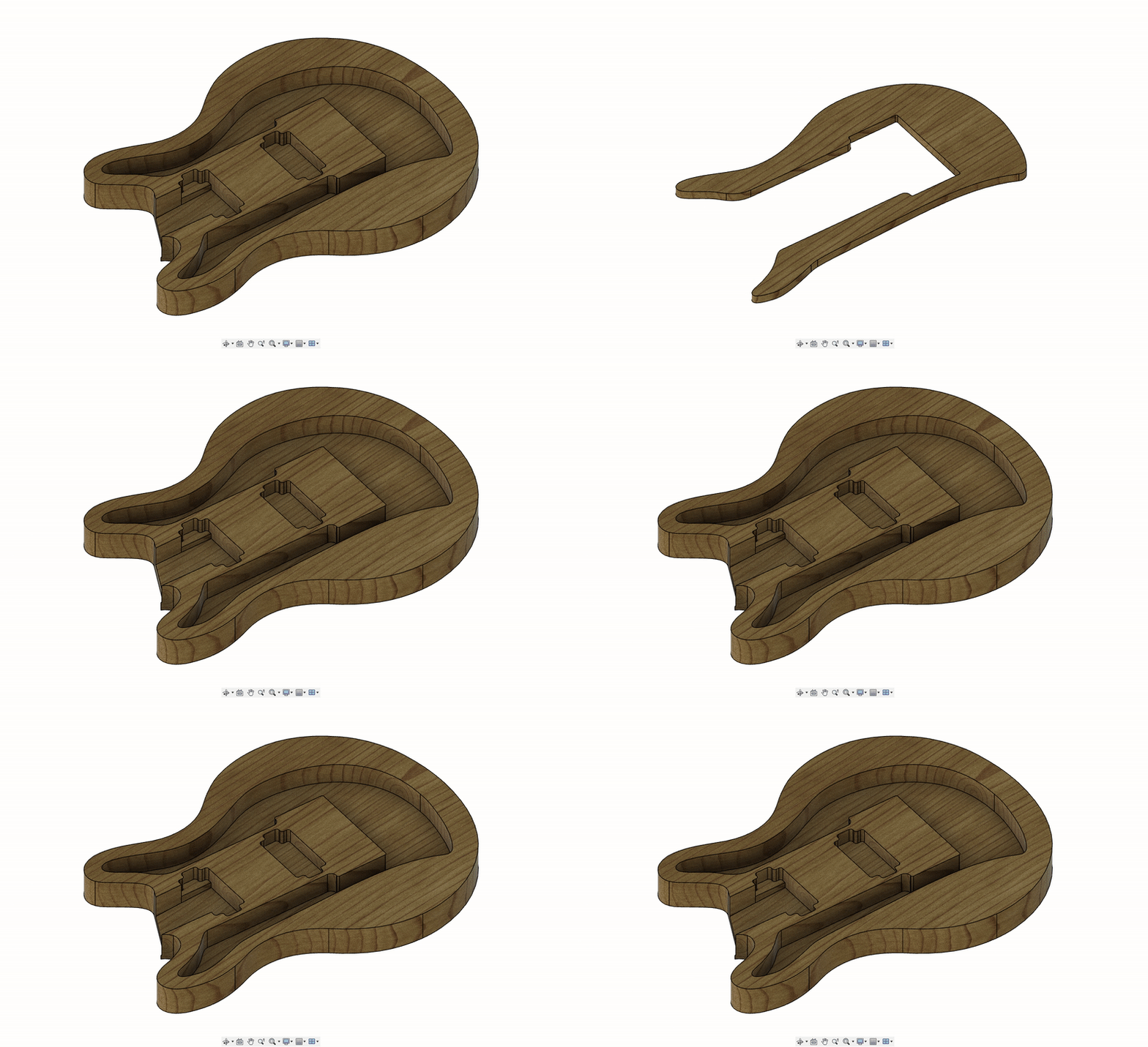
Once an outline had been agreed on and offered up against one of Simon’s guitar bodies to check properly, I started turning the basic drawing into a set of templates to facilitate the precision routing of parts. These templates would be lasercut out of MDF or acrylic and are usually stuck onto the wood blank to guide the router around the shape of the component. There were at least three body templates needed, each containing different features that would be routed to different depths. Firstly, there was the outer body profile to provide the basic shape of the guitar. A neck pocket template would be needed to cut the joint area – the precision of this template was particularly important as it had to align perfectly with the taper of the guitar neck to ensure the two would mate perfectly. Then there were cavity templates which would be used to hollow out large sections of the body for weight reduction and to hide electronics. This should have been a simple one to make, but once again the reference material was very difficult to translate into accurate plans, being a photo of the guitar body taken at quite an awkward angle.
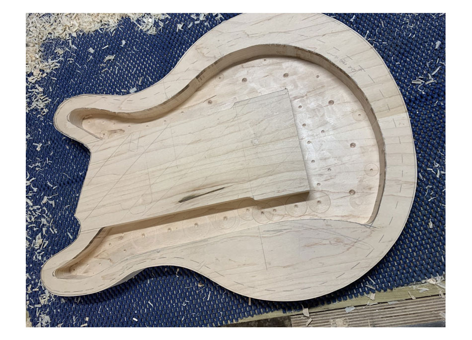
As I’d become quite accustomed to by this point, I used Photoshop to distort the image so the perspective would match that of my drawing. It was far from perfect, but I got it close enough. Thankfully there wasn’t much precision required as the cavity was mostly just for weight reduction, with no critical dimensions. One of the hardest parts of the project for me was understanding that not every industry requires micron-level tolerances, and to keep up with the large workload I would have to get used to making things less accurately than I would typically be happy with.
