Banshee Guitars Client Project (NLT2)
Following on from my contribution to Banshee guitars in Semester One, Simon continued to work on the physical guitar build, while his nephew Luke (developer) began work on an augmented reality (AR) app so that prospective customers could view an interactive 3D model of the guitar. A few months down the line, it was time for me to get involved again and complete the unfinished elements of the project (plus some new tasks). The continuation of this client project formed half of my NLT tasks for Semester Two, the other half being the Negotiated Design Final Project; both took roughly the same time to complete, and along with the Portfolio and Dissertation, kept me very busy – time management can be found further down this page. Please click here for the updated NLT2 form. Here is a recap of the work completed in Semester One:
Converted paper plans into digital technical drawings
Produced templates for routing the guitar body, neck, headstock and fretboard
Produced a 3D model of the guitar body, neck, headstock and fretboard
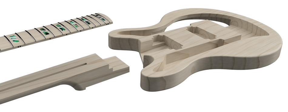
In January 2022, the model looked like this:
Following on from my contribution to Banshee guitars in Semester One, Simon continued to work on the physical guitar build, while his nephew Luke (developer) began work on an augmented reality (AR) app so that prospective customers could view an interactive 3D model of the guitar. A few months down the line, it was time for me to get involved again and complete the unfinished elements of the project (plus some new tasks). The continuation of this client project formed half of my NLT tasks for Semester Two, the other half being the Negotiated Design Final Project; both took roughly the same time to complete, and along with the Portfolio and Dissertation, kept me very busy – time management can be found further down this page. Please click here for the updated NLT2 form. Here is a recap of the work completed in Semester One:
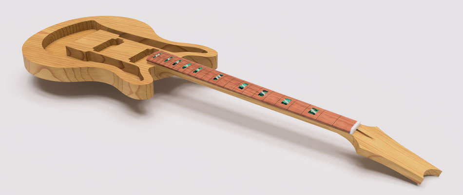
In January 2022, the model looked like this:
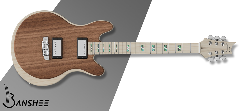
By April 2022, the model looked like this:
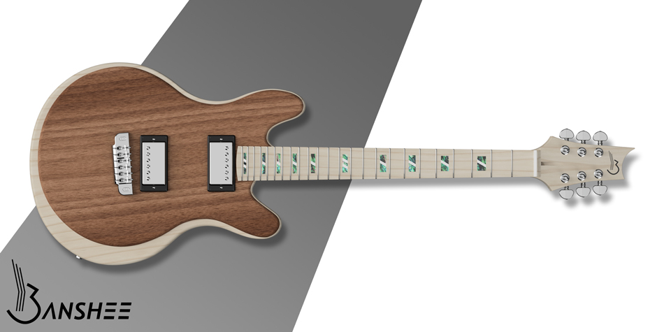
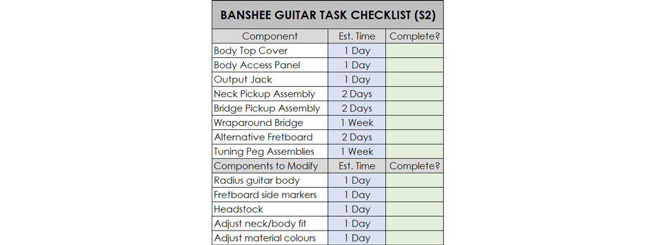
Here I will be showing how I got from one to the other. The project recommenced when Simon emailed me a complete list of components that needed to be modelled to finish the guitar, which was a bit overwhelming as I had just started planning my own personal project too. In order to keep things organised and work out how to best use my time, I made a checklist of the parts that I was required to model, with estimates of how long they would take based on their apparent complexity. I had hoped that some of the complex components like the wraparound bridge might be available to download pre-made online, but I was unable to find any suitable models which meant everything would have to be built from the ground-up; as before, Simon did not supply any dimensioned drawings. All 3D models were created using Fusion 360.
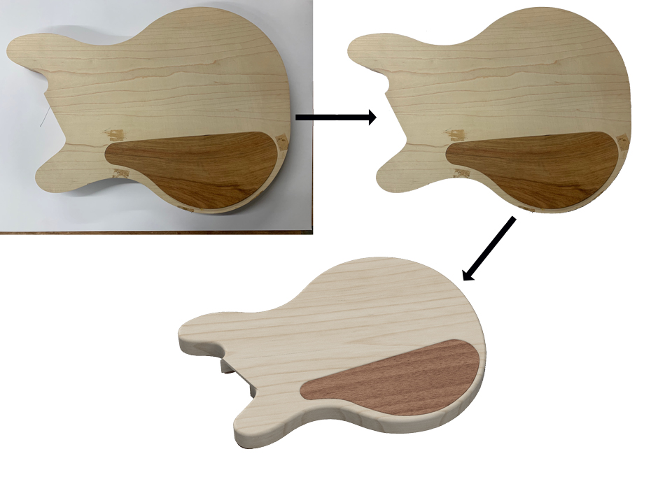
I began by completing the guitar body, since it was at the centre of the model and very important to get right from the start. This included creating the front and back covers which would be fixed to the hollowed-out body to keep the components inside. All that Simon provided to model these parts were a few photographs showing them on the real guitar – no dimensions, as I had become accustomed to. I edited these images using Photoshop so they were as flat and true as possible; I would be tracing around the shapes so any distortion would lead to a misshapen part.
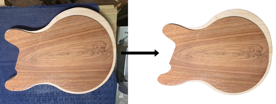
The image didn’t fit my model perfectly due to the angle that the photograph was taken at, but it was close enough to trace around and obtain a fairly accurate outline of the top cover – precision was not a priority, the component only needed to cover up the open body cavities.
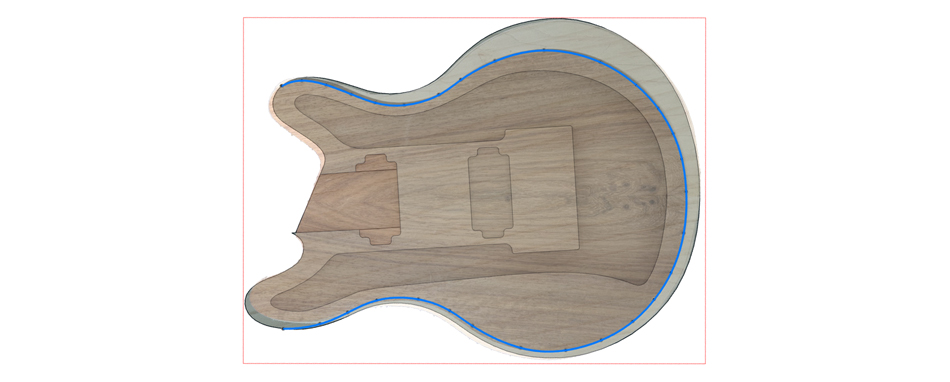
I couldn't tell from the source image if there was meant to be a slither of light wood showing all the way around the top cover, of if it went right to the edges in some areas. I emailed Simon an image of what I had created to see if it was right. It was important to regularly get approval of the designs to make sure I wouldn’t have to go back and alter things later on.
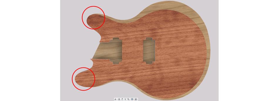
Simon confirmed that there was meant to be some of the light-coloured wood body visible around the edges, so I altered the top cover accordingly. It was also at this point that we discussed the colouration of the model since Simon wasn’t happy with the materials I had chosen. I made some adjustments based on his recent photographs, successfully matching the wood tone of the real guitar. In hindsight, I should have sorted this out much earlier - it didn't take much time to work out the right colours to use, but I then had to go and apply the changes to all of the seperate parts which was inconvenient.
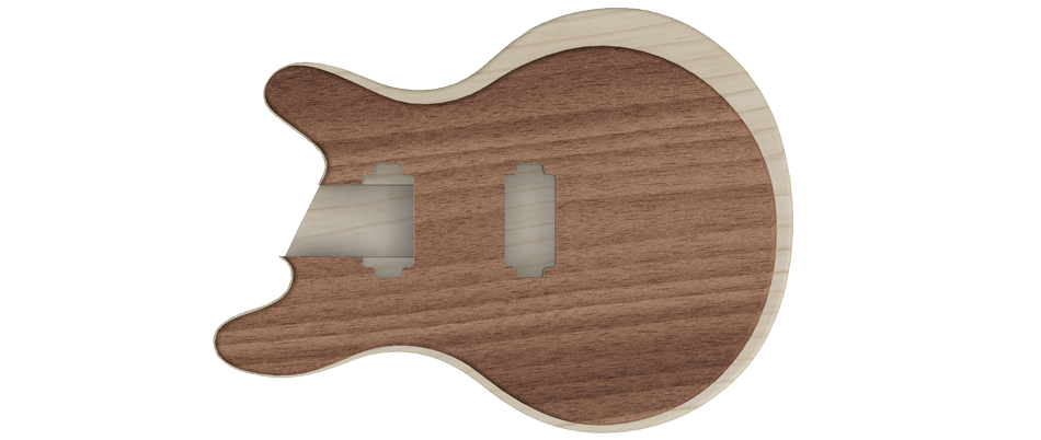
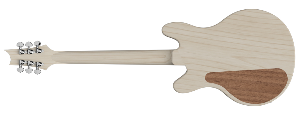
The back access cover was very much the same process – edit reference image, trace around, extrude 3D component, and fit to model. It was also at this stage that the body and top cover had a smooth radius added to the edges for user comfort.
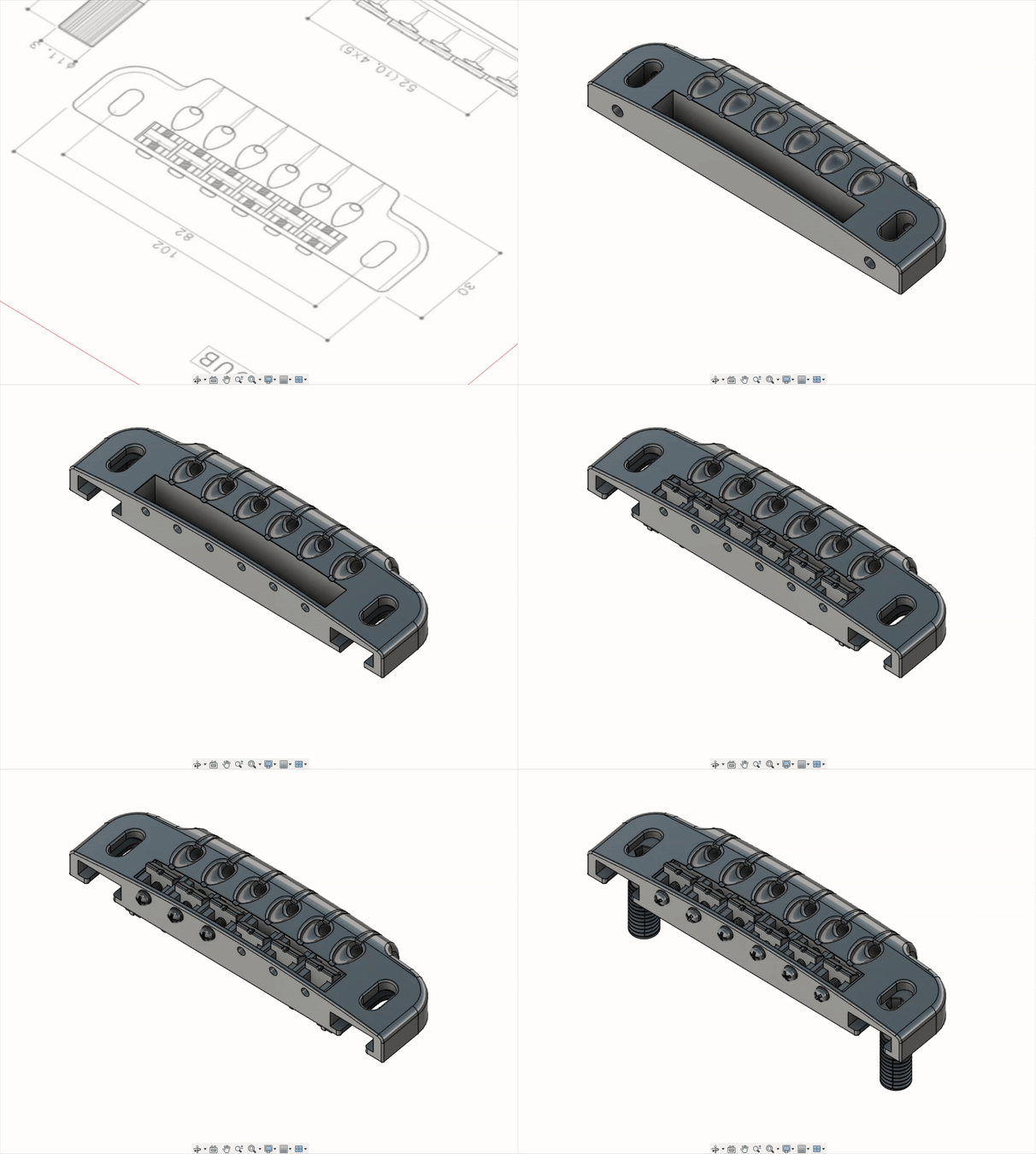
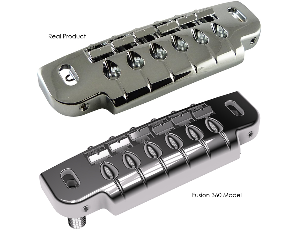
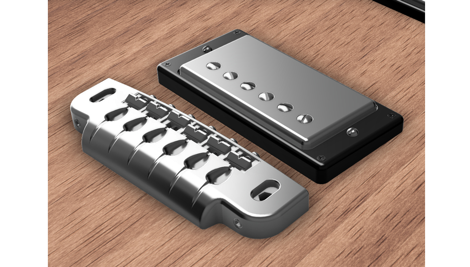
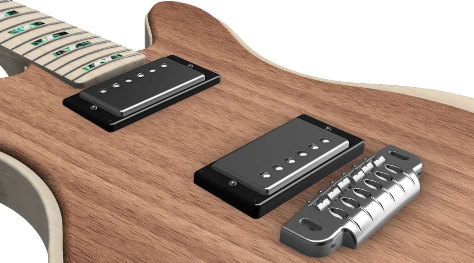
Next I moved onto the various electronic components to add to the body. This was done purely for product visualisation purposes, to help show a realistic product to the prospective customer. The electronic parts themselves would be ordered in, not made by Simon, so they were purely decorative but still important to model accurately for the sake of realism. I started with the most complex component, the Gotoh 510UB Wraparound Bridge, which Simon had selected for his build. I had hoped to save some time and find a pre-made model online, but all I found was a technical drawing. This was still very helpful, and allowed me to create a fairly accurate 3D-model. This was the most complex component I crafted for this project, and I really enjoyed building it - I feel I have developed quite a valuable skill in translating drawings (with zero or limited dimensions) into accurate models.
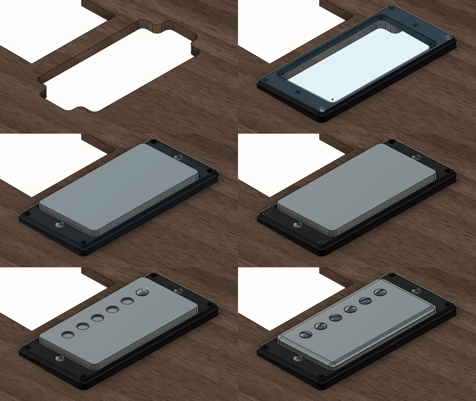
With the bridge modelled and fixed to the body cover, I moved on to the two humbucker pickups, one placed at the bridge and one at the neck. Simon provided some reference images to work from, and to save time I decided to create one model to then duplicate and adjust, rather than make the two parts separately. The finished components were positioned as per Simon's reference drawings, and then mated to the top cover. I sent him a series of images to make sure he was happy with the parts.
The final body component to model was the output jack, a small 1/4" port to connect the guitar to an amplifier. Once again I worked from a reference image to replicate the part as best I could without a real technical drawing. I had to keep in mind that all this was purely for visual effect, so time spent in the pursuit of absolute precision would be wasted. As mentioned in the Semester One write-up, this was one of the more challenging parts of the project for me; I am a bit of a perfectionist, and found it frustrating to produce parts that weren't dimensioned or toleranced properly. It was a learning experience to understand that different industries have very different standards and requirements, and that you have to work to the client's needs, not to your preferences as a designer.

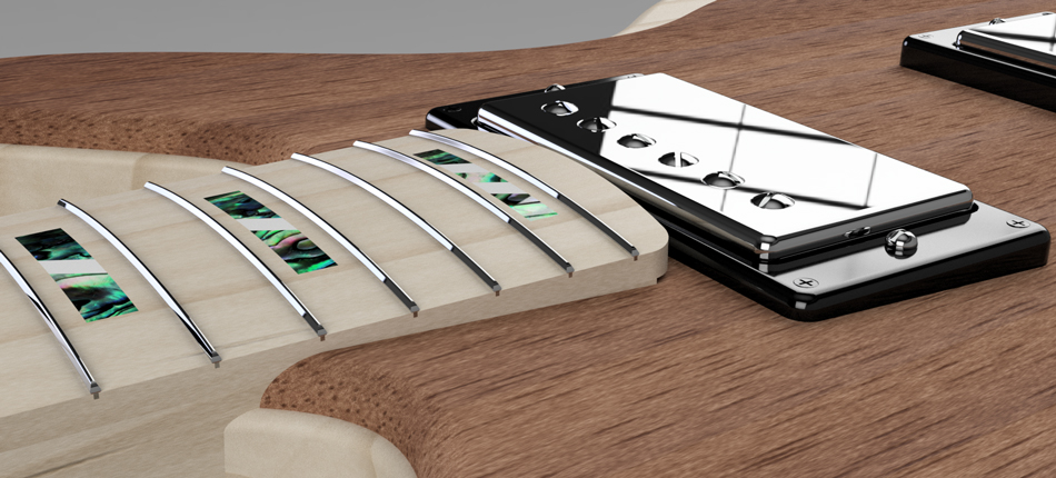
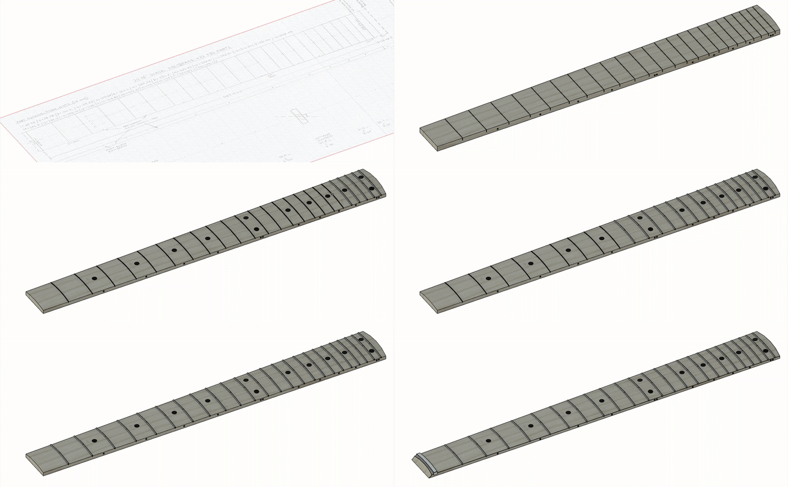
Next, there was a lot of work to do with the fretboard, such as adding in the individual fret wires. Usually when faced with a repetitive task like creating 24 identical items in a model, a pattern tool can be used so you only need to design one part and then replicate it along a path or in a geometric pattern. Unfortunately, the fretboard was both tapered and curved, meaning that the fret wires at one end would be different lengths and shapes to those at the other end and a pattern tool would not work. I had no option but extrude each wire individually. While this took a long time and was quite frustrating, the end result was a very realistic fretboard which accurately represented hand-fitted wires. I also added some fret markers on the side of the board while doing this, as requested by Simon.
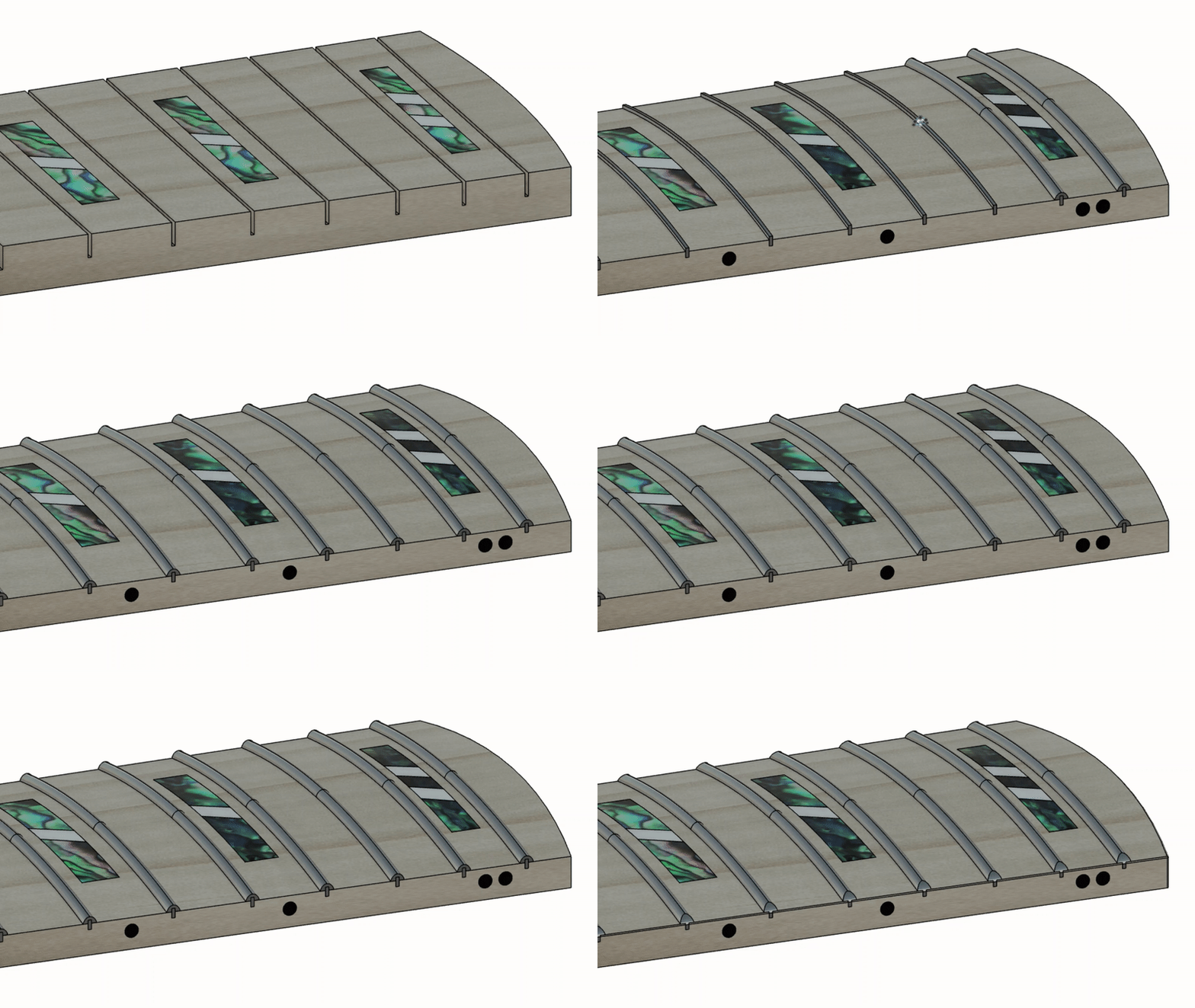
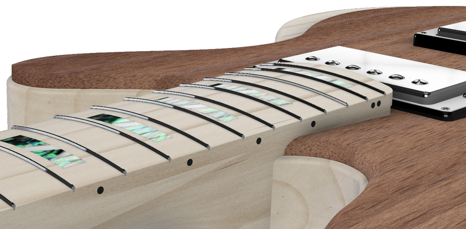
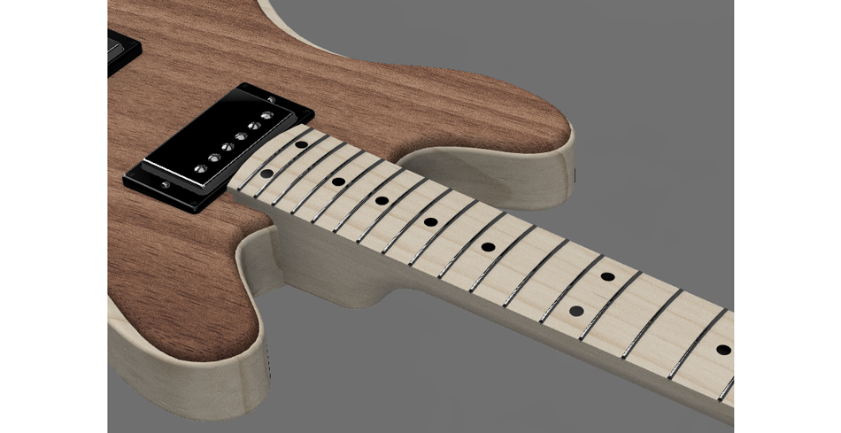
The final step to complete the fretboard was to create an alternative pattern of fret marker. This was to be used within the AR app (developed by Luke) so that the customer could view both and decide which design they liked. Simon asked for a simple design with black dots replacing the fancy abalone shell and mother of pearl markers.
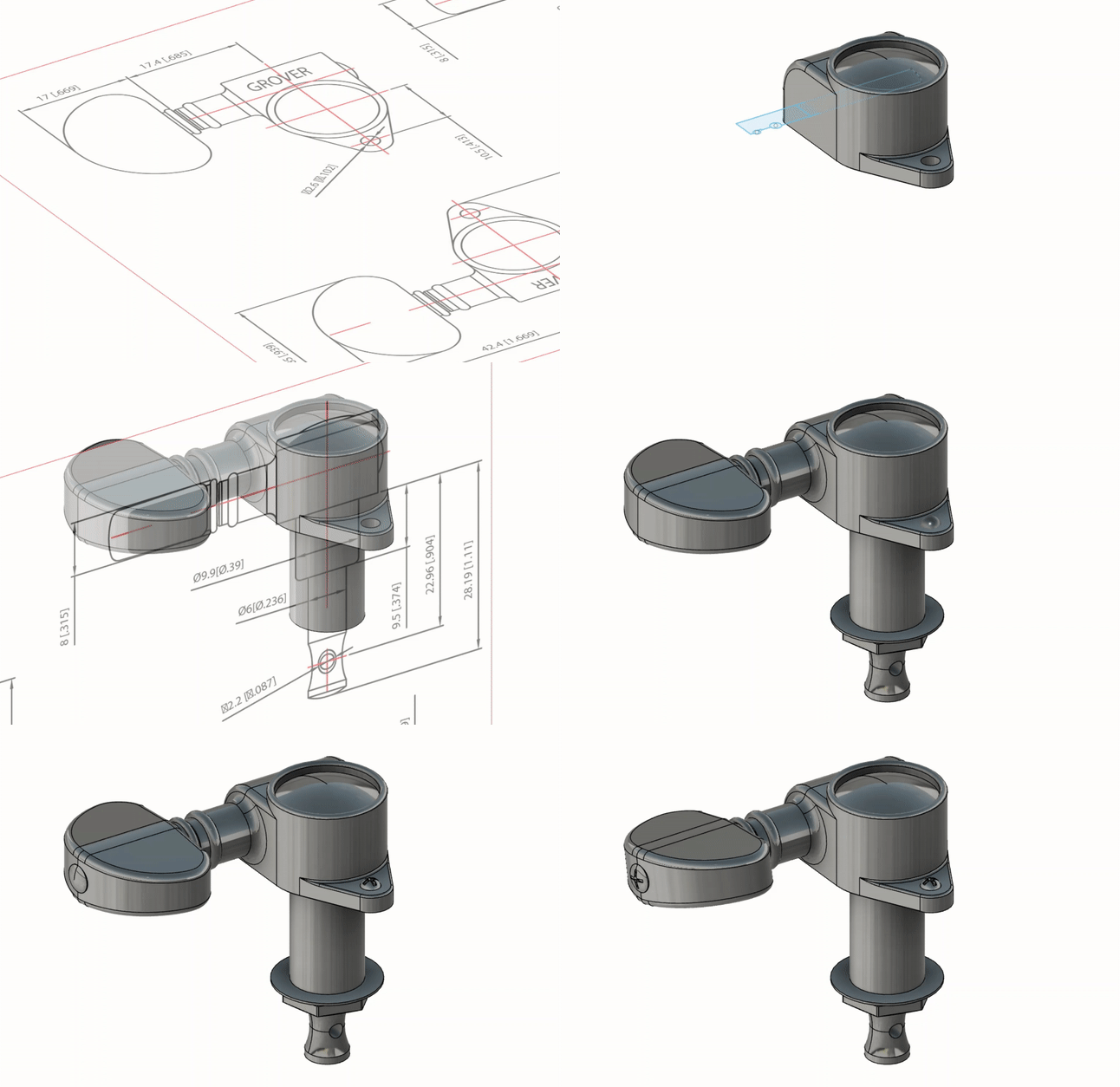
The next part to finalise was the headstock, complete with its six tuning pegs. Similarly to the wraparound bridge, the pegs were complex parts and I had hoped that 3D models of them already existed – unfortunately I couldn’t find any free files, and to make matters worse there were very few technical drawings available for the specific peg design that Simon wanted. Thankfully Simon was able to send a drawing which had a few basic dimensions on, and that was enough for me to extrapolate the rest and create a fairly accurate model. I duplicated and mirrored the finished peg since they come with 3 for one side of the headstock and 3 for the other.
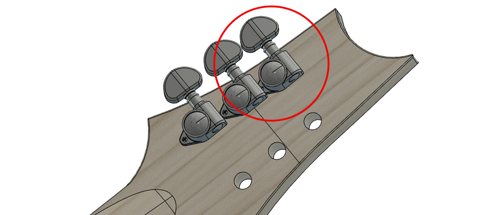
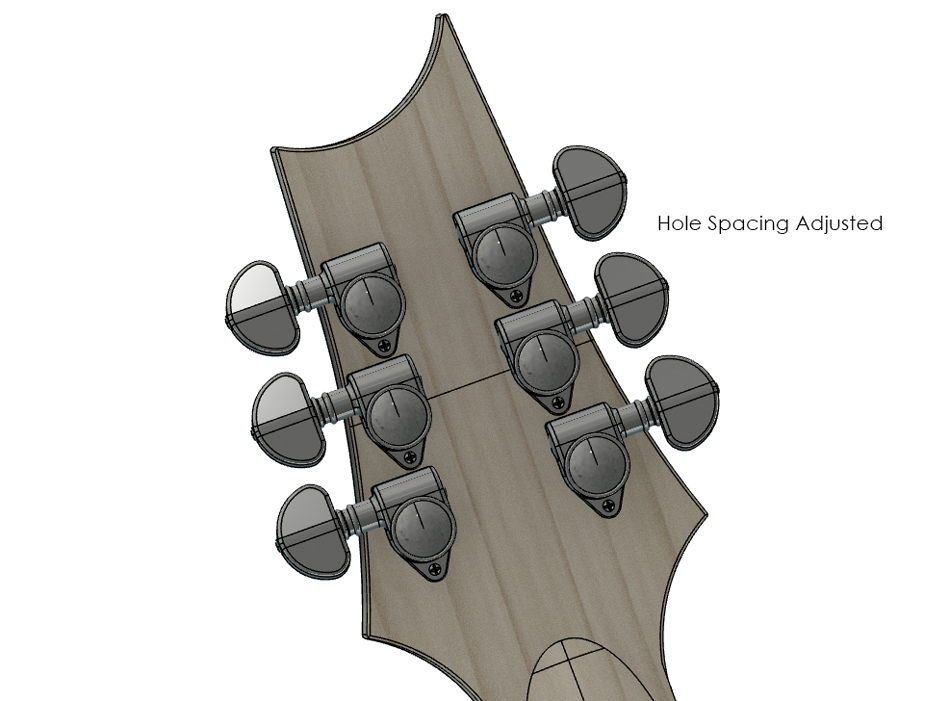
To accommodate the new tuning pegs, the headstock needed some holes cut through it in the right positions. To ascertain the correct positioning, I looked though the plans that Simon sent to me at the start of the project and found a headstock drawing that had the holes marked. This was then used as a template to cut the six holes for the pegs – it quickly became apparent that there was a problem. The holes were too close together, so the pegs would interfere with each other when fitted. I suggested to Simon that he should either chose a smaller peg design (which would be a shame since my model would be wasted), or instead I could simply space the holes out appropriately to fit the current pegs. Luckily, he was happy with me adjusting the position of the holes.
The final modification requested for the headstock area was the addition of the Banshee logo. I decided that the full logo would be a bit of a squeeze, so I removed everything but the ‘B’ and cut it into an empty space on the headstock before colouring it in with a darker material so it would stand out.
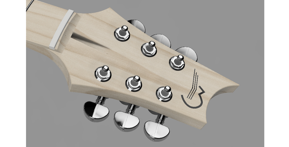
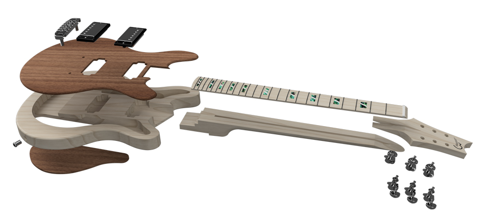
To complete my side of the project, the final tasks were to produce high-quality renders which could be used for advertising, and to export all the models in formats that could be used by Simon and Luke in the future. For example, Simon had hoped to use the models to CNC machine some parts like the neck, so the most appropriate file to use would be STEP. Fusion 360 archive files were also created so Simon could modify the models in the future, although he would need to obtain the software. For Luke, FBX files would allow him to take the model into Unreal engine or Unity to use for his AR app. All of these files were added to a private Dropbox folder that I was given access to by Simon. I cannot link to this, so I have also created a Google Drive folder to act as a final handover document, which can be accessed here. Below are the final renders produced using the native Fusion 360 rendering suite, including an exploded view to show how the parts fit together. Click to open full size.
Below is a video demonstrating the fantastic augmented-reality app created by Luke, which features a range of different customisation features so that customers can spec their guitar to their liking. It was absolutely amazing to see my model come to life and actually serve a practical purpose; it certainly made all of the extra work on the little details worthwhile. Many thanks to Luke for originally putting me in contact with Simon – you can take a look at his work here.
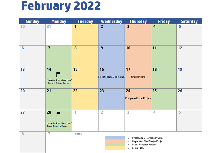
With Luke coding the AR app, Simon physically building the guitar, and me doing the design work, this was truly a collaborative effort, and one that required dedication and planning from all involved to obtain the best outcome. The project ran very smoothly for the most part, and communication between the client and I was always efficient and clear. If I was able to do this project again, I would have made an effort to start on phase two of the project sooner. I should have been more proactive in getting things moving rather than waiting to get the go-ahead from Simon. By the time that I had established what needed to be done and actually made a meaningful start, it was already March, and I was then juggling between this project and my own personal final project in addition to the other modules. I had created a time planning document that took all the modules into account, but it did not account for this project running on later than March (see below for a page from my module planning document). Overall, however, the project was a complete success, and all of the original objectives were met. Simon expressed that his expectations had been exceeded by a considerable margin.
